
Cutoff Frequency: There are two cutoff frequency in band pass filters i.e. Lower cutoff ω c1 & upper cutoff ω c2 , any frequency before ω c1 and after ω c2 is being blocked by the filter. Bandwidth: The total range of the allowable frequency is known as bandwidth, from lower cutoff to upper cutoff frequency. β = ω c2 – ω c1
Aug 17, 2020 · A simple capacitive low pass filter with one resistor and one capacitor has a cutoff frequency of . Substituting the corresponding R and C values, the cut off frequency would be 45.473 Hz. So, the output will be 70.7% at 45.473 Hz.
Aug 31, 2020 · Steps to create the residual plot and calculate the cutoff frequency: 1) Filter the raw data at each frequency over the test range. Based on some past analysis, I thought the ideal frequency would be between 2.5 and 6 Hz so I tested every frequency between 1 and 10 Hz at 0.1 Hz intervals
Jun 24, 2015 · MrChips. Joined Oct 2, 2009. 25,930. May 16, 2018. #2. If R is relatively large compared to the reactance of L and C, then you can eliminate R from the circuit. You are left with an L-C circuit which will have a resonance frequency (not a cut-off frequency). ω2 = 1 LC ω 2 = 1 L C. Like Reply.
The cutoff frequency is characteristic of filtering devices, such as RC circuits. At this point, the amount of attenuation due to the filter begins increase rapidly. An example of this is shown in Fig. 1 below. This RC circuit has a time constant of 0.01 sec. Fig. 1. Bode Diagram with Cutoff Frequency
How to design a Butterworth filter with a cutoff frequency other than ω c = 1? [22] This is done by scaling the normalized filter up to the desired cutoff frequency, simply by replacing ω with ω/ω c in H n (ω). Equivalently, we can scale our filter in the s domain by replacing s with s/ω c in H n (s). Another parameter that we want to control is the gain; this is the amount the frequency is changed in amplitude at a given frequency.
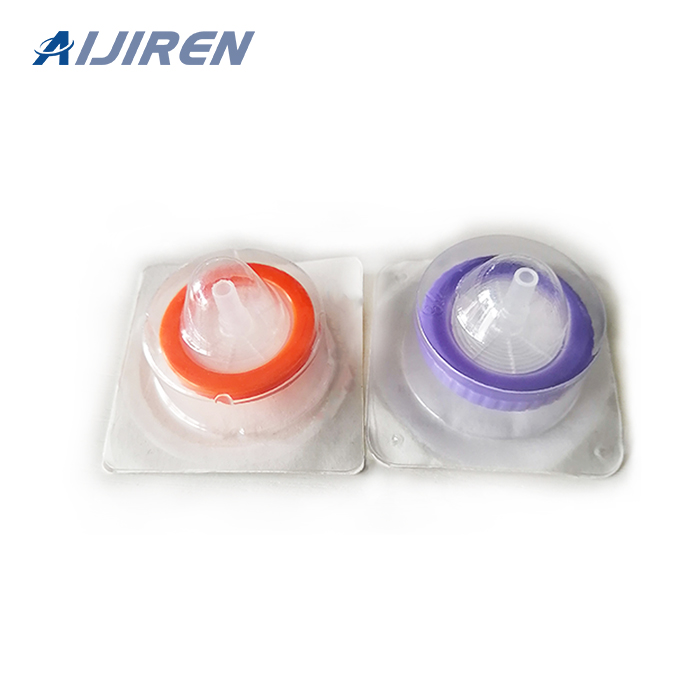
Sep 28, 2016 · Load the sample into the syringe. Attach the filter securely with a twisting motion. With a luer slip syringe, this is about one quarter turn as the filter is pushed on. If the syringe has a luer lock (as in this example), fix it firmly but do not over-tighten. Hold the assembled syringe and filter vertically to wet the membrane evenly.
Dec 06, 2017 · I want to know factors that are needed to be considered in designing a filter which is to be implemented with a pure sine wave Inverter. The following figure is the output waveform of the inverter across a resistive load without filter. I understand that the cutoff frequency must be below the switching frequency and above the fundamental frequency.
Oct 16, 2007 · understand what the cut off frequency is. My confusion was that I though the natural frequency was the cut-off frequency. In other words, I though the transfer function would be 0.707 at the natural frequency. What I've seen recently, is that this statement is close to being true if the system is under damped, and further from true if the
Hold the syringe with the filter pointing up and “top off” by pushing a few drops through the filter. Place the filter tip over the collection container and push the sample through a syringe filter by applying gentle positive pressure. To purge the syringe filter and maximize sample throughput, remove the filter from the syringe and draw air into the syringe. Then reattach the filter and push the plunger to force some of the air through the filter.
Design a lowpass FIR filter with a cut-off frequency of 3 kHz. The filter is to be used with a sampling frequency of 12 kHz and is to have a ‘length’ of 11, i.e. 11 coefficients are to be used. (b) Redesign the filter, so as to reduce the passband ripple, by using a Hanning (N.B. not Hamming!) window. 2. Design a highpass FIR filter with
Jul 11, 2017 · If the signal is sent through a low pass filter and cut of is set to 700hz. Then the frequencies above 700hz will be attenuated or removed completely hence they will fall under the category of stop band. In simple words, a band of frequencies that is stopped by the filter to pass though is called the stop band. Cut-off Frequency.
Step 2: Attach a syringe filter to the Syringe. Open the syringe filter package so that you can later pick the filter up easily, especially for individually packed sterile syringe filters. a. For sample volume < 10 mL. Draw a small amount of air (about 1 mL) into the syringe before loading the sample solution.
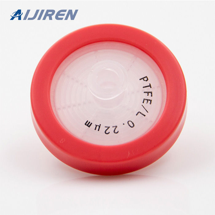
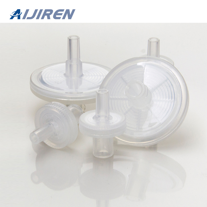
Syringe filters are single use, self contained, filtration devices that are typically used to remove contaminating particulate from liquids or gasses. When selecting the correct syringe filter for an application there are a number of factors to consider, these include: Filter and housing materials. Pore size.
The former filter design tries to “block” the unwanted frequency signal while the latter tries to short it out. The cutoff frequency for a low-pass filter is that frequency at which the output (load) voltage equals 70.7% of the input (source) voltage. Above the cutoff frequency, the output voltage is lower than 70.7% of the input, and vice